
In Part 1, I proved it was possible: I used a CYD to reverse-engineer the Truma LIN/TIN-bus protocol and control my boiler from a phone. It was a great proof of concept but, with a bigger screen, a more powerful processor and a lot of more PSRAM, it could be much improved.
It cost me six weeks of deep-dive engineering: a brand-new ESP32 platform, a complete build system overhaul, a cloud tunnel to escape CGNAT, support for an extra BLE device for fresh water level monitoring, and a safe OTA updater that won’t brick the system mid-download. Here is the full story of how it came together.
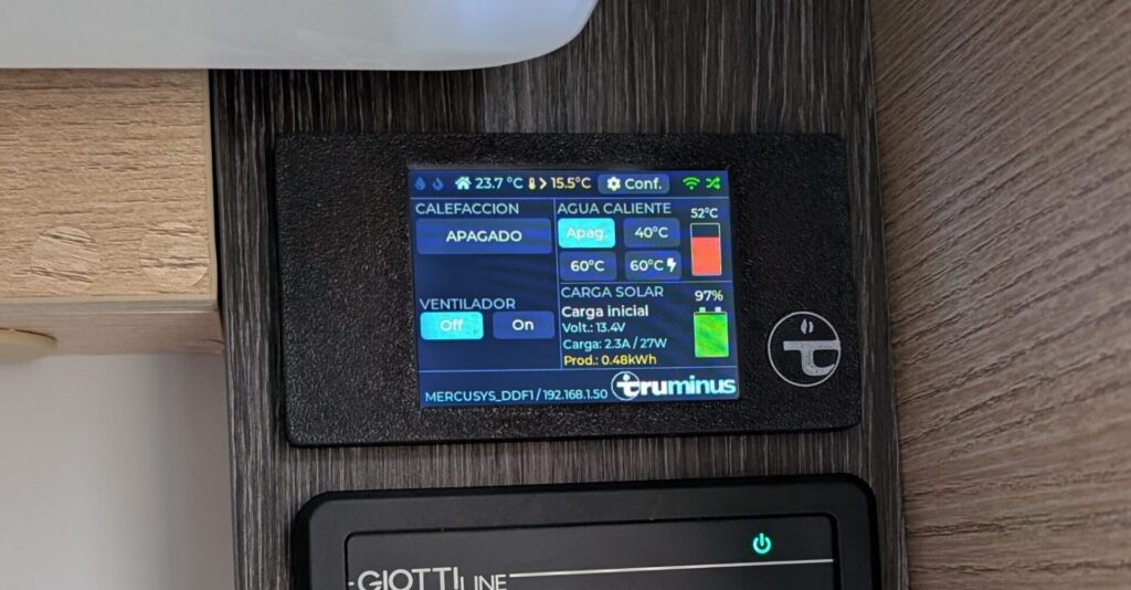
The original CYD-C5 display
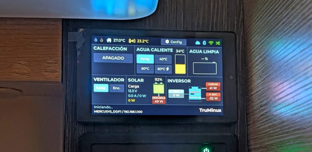
The new JC4880P443C display
Phase 6: Hitting the Wall with the Cheap Yellow Display
The CYD-C5 is a wonderful little board for the money, but I kept bumping into its ceiling. The 2.8″ screen was cramped once I started adding solar and battery data. Moreover, the C5 was still a small single-core part. If I was going to live with this panel for years, I wanted room to grow.
Phase 7: The Big Leap — ESP32-P4 and a Proper 4.3″ Display
The new home for the project is a board called the JC4880P443C, built around Espressif’s ESP32-P4. On paper it’s a different league:
- Dual-core RISC-V at 400 MHz — I can pin the blocking LIN serial task to one core and let WiFi, the web server and the screen breathe on the other.
- 32 MB of PSRAM and 16 MB of flash — enough to hold a full framebuffer in memory and stop counting kilobytes.
- A 4.3″ 800×480 ST7701 RGB panel with GT911 capacitive touch — more than four times the pixels of the CYD-C5.
There’s a catch, and it’s a big one: the P4 has no built-in WiFi or Bluetooth. Radio is handled by a separate ESP32-C6 co-processor that the P4 drives over a high-speed SDIO link. Two chips, two firmwares, one device. That architecture would later cause some of the most interesting bugs in the whole project (more on that below), but it also meant I could eventually update the radio chip’s firmware through the main chip, over the air.
Phase 8: Leaving the Comfort Zone — From PlatformIO to ESP-IDF
The CYD firmware was built on the Arduino framework through PlatformIO — friendly, forgiving, and full of ready-made libraries. The P4 is so new that most of that ecosystem simply doesn’t support it yet. So I took the plunge and rewrote the entire build on Espressif’s native toolchain, ESP-IDF 6.0, driven by idf.py.
This was not a free afternoon. It meant swapping Arduino’s comfortable String and JSON helpers for lower-level C/C++, replacing the web server stack, and learning a long list of P4-specific quirks the hard way: linker settings for early silicon, an internal-RAM budget that had to be measured and trimmed, a USB serial console that fought me for control of the port, and a TLS engine whose hardware cryptography produced subtly invalid signatures on this chip revision — which I eventually had to disable in favour of software crypto. Every one of those traps now lives in a written “skill” file in the repository so I never have to rediscover it.
Lesson learned: when you adopt brand-new hardware, budget most of your time for the toolchain, not the features. The heater logic from Part 1 ported over in an afternoon. Getting it to build and flash reliably took weeks.
Phase 9: The Display, Reborn
With four times the pixels, I rebuilt the user interface from scratch in LVGL, the embedded graphics library. The screen is now three clean bands:
- A top bar with the outdoor temperature, a settings gear and live status dots (cloud, Bluetooth, WiFi, LIN)
- A central dashboard split between the heater controls and the energy panels
- A bottom status bar with the network name and IP.
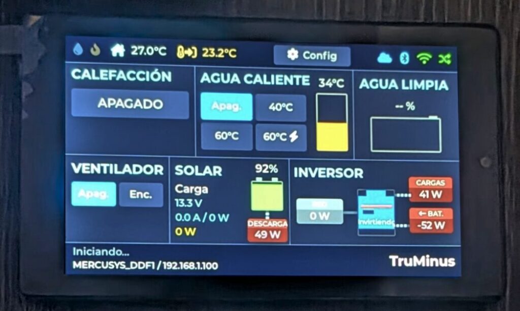
I used FontAwesome icons rendered as a custom font subset so the controls look like real product UI rather than a hobby project — thermometer, flame, fan, water drop, solar panel, battery. Little touches crept in over the weeks: caret triangles for the setpoint and fan controls, a boiler “thermometer” gauge, animated power-flow lines between the solar/battery/inverter panels.
Phase 10: A Real Web App
The phone interface got the same treatment. Instead of embedding the web files inside the firmware binary, they now live in their own 8 MB filesystem partition and are served by the P4’s native HTTP server over a WebSocket connection. A build step automatically gzip-compresses every asset and stamps a version hash on each file, so browsers always refetch what changed and never serve a stale cached panel.
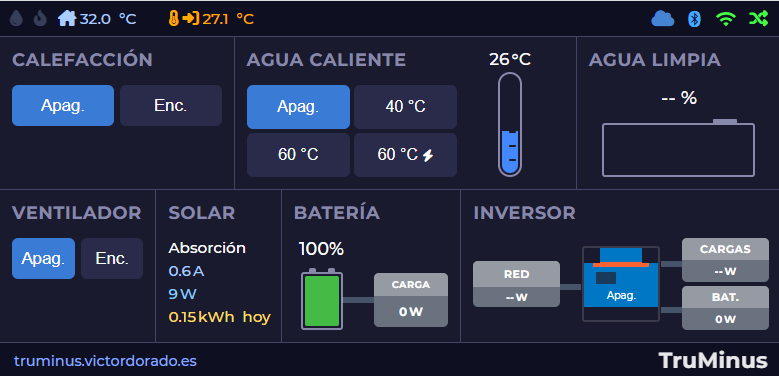
Crucially, the web UI now mirrors the physical screen: the same layout, the same panels, the same live data, kept in sync over the WebSocket. Touch the LCD and the phone updates; tap the phone and the LCD follows. It’s a Progressive Web App too, so it installs to the home screen like a native app, and it reflows cleanly from a desktop browser down to a phone in portrait.
Phase 11: Escaping CGNAT — A Cloud Tunnel of My Own
Here’s the problem that nearly stopped the whole project: my motorhome connects through a mobile router, and like most cellular connections it sits behind Carrier-Grade NAT. There is no public IP address to forward a port to. From the open internet, the panel is simply unreachable. Every “just port-forward it” tutorial is useless here.
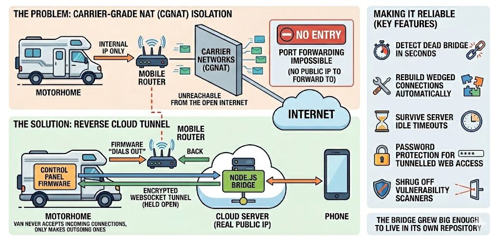
The solution was to build my own secure reverse tunnel. A small Node.js bridge runs on my web server with a real public address; the firmware “dials out” to it over an encrypted WebSocket and holds the connection open. When I open the panel from my phone, my request goes to the cloud server, down through the tunnel, into the van, and back. The motorhome never needs to accept an incoming connection — it only ever makes outgoing ones, which CGNAT happily allows.
Making that reliable over a flaky mobile link was its own saga: detecting a dead bridge in seconds rather than minutes, rebuilding a wedged connection automatically, surviving the server’s idle timeouts, adding password protection for the tunnelled web access, and teaching the bridge to shrug off the endless background noise of internet vulnerability scanners. The bridge eventually grew big enough to live in its own repository.
Phase 12: More Senses — Inverter and Fresh Water Tank Level
With memory to spare, I kept adding data sources. The panel now reads, in addition to the solar charger and battery BMS from Part 1:
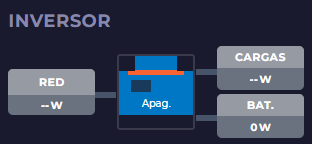
- The Victron Multiplus inverter/charger over Bluetooth, showing live power flow in and out of the AC side — with animated arrows for charge vs. discharge.
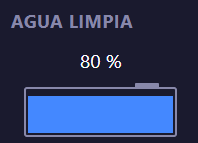
- A wireless fresh-water tank sensor using the open BTHome standard.
Getting Bluetooth reception solid through the C6 co-processor took real detective work — modern Victron devices broadcast using BLE 5 “extended advertising”, which I had to explicitly enable, and I had to widen the scan window to claw back range that the radio chip was losing to WiFi coexistence. I added a serial scan command just to see, live, which devices were in range and how strong their signal was.
Phase 13: Updating in the Wild — Over-the-Air, Without the Fear
If I’m going to fix a bug while the van is parked, I need to push new firmware over the air — and I absolutely cannot afford for a half-finished download to leave the panel dead.
The system pulls releases straight from GitHub Releases, compares versions, and only nags me for a manual update on meaningful (minor/major) releases rather than every tiny patch. The download streams directly into a spare flash slot. The clever part is the safety net: after flashing, the new firmware boots into a probation period. It has to prove it can actually start up, get an IP and keep enough memory free; if it can’t, the panel automatically rolls back to the previous version on the next reboot. A bad update heals itself.
It can even update the web interface assets separately from the firmware, and reflash the ESP32-C6 radio co-processor through the main chip when their versions drift apart. Getting all of this stable over a slow mobile connection meant a long tail of fixes: pausing Bluetooth during downloads to free up memory, adaptive download throttling so the SDIO link to the radio chip wouldn’t choke, and keeping the cloud tunnel alive through the whole process so I can watch progress remotely.
I have, genuinely, never been so relieved as the first time a remote update completed, rebooted, and reconnected on its own.
Phase 14: Reorganizing the code and the knowledge
The code was a little bit unorganized after many tests, so it was refactored to a more modular system with test coverage. First, the tricky decoding logic — the byte-level parsers for every Bluetooth device, the LIN protocol checksums, the fault-log encoder — was pulled out into hardware-independent modules with automated tests. I can now verify the math that interprets a Victron broadcast or a heater frame.
Second, the repository now carries a set of detailed “skill” documents — one for the build-system traps, one for each Bluetooth protocol, one for the cloud tunnel, one for the OTA system, one for the Truma LIN frames. Every painful lesson is captured the moment I learn it, so the next time I (or anyone) touch that corner of the code, the landmines are already mapped. It’s the documentation I wish every hardware project shipped with.
Conclusion: From Proof of Concept to Daily Driver
Part 1 proved I could talk to the heater. Part 2 was about everything that turns a clever demo into something you trust with your family’s hot water on a winter night, hundreds of kilometres from your workbench.
- A bigger, dual-core brain with room to grow.
- A proper 4.3″ interface mirrored to a phone-friendly web app.
- A self-built cloud tunnel that punches through carrier NAT.
- A full picture of the van’s energy — solar, battery, inverter, water, weather.
- An over-the-air update system with a parachute, so I can keep improving it without ever opening the panel again.
The result is something that offers: global remote control and far richer telemetry than the original hardware, on a panel I can extend at will.
The project is open source. If you want to dig into the code, the protocol notes, or the cloud bridge, it’s all on GitHub — and I’d love to hear from anyone tackling the same problem in their own van.
